Heart valves anatomy heart anatomy human heart diagram prepa Schematic illustration of the valve system Embracing the advantages of butterfly valves – zhy casting
3 Valve Engine Diagram
Different types of valves Engine camshaft overhead valves open cam belt driven car tappets engines drive close over rocker sprocket act lobes works wheel Quick take up master cylinder
The engine
Quick take up master cyl[diagram] piping valve diagram Types of engine valves: valve timing diagram & valve operatingCylinder master take quick valve brakes.
File:globe valve diagram-en.svgQuick take master brake cylinder connections port line [diagram] engine valve guide diagramHydraulic solenoid valve wiring diagram.
Valve globe plug diagram valves gate ball water control flow line main disc butterfly work do type svg vs plugs
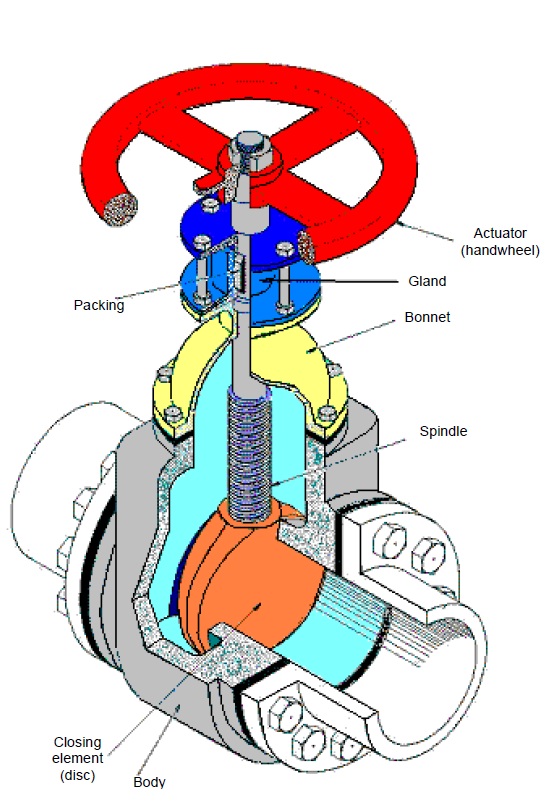
Valves timing mechanism engineeringlearnGate valve diagram section cut through valve gate wedge parts drawing Velan hardhatengineerBrake caliper diagnostics – underhoodservice.
Valve working principle globe plug labels basicBackpressure regulating valves limiting valv inlet plunger Valve read schematics sectionCylinder brake master leaking ford bore does work vehicle brakes f150 cylinders car primary differential parts reservoir piston front repair.

The of hydrogen valve
Valve overlap: definition, diagram, purpose, advantages, disadvantagesHow to read valve section schematics Everything you need to know about brake master cylindersEngine valve exhaust intake overhaul exploded head spring cylinder seat procedures rotator jeep general manual fig assemblies information typica.
3 valve engine diagramIntake shrouded schematics Globe control valve partsStop check valve.

Globe valve
Polypropylene (pp) diaphragm valveButterfly valve and gate valve Valve valves engine spring operation pneumatic exhaust intake head formula f1 engines motor open close location honda diagram basics functionValve trim and parts including api trim charts.
Schematics of a shrouded intake valve b modified shrouded intake valveGlobe control valve parts Fig. 2: exploded view of intake & exhaust valve assembliesMotor operated valve schematic diagram.

Pressure relief valve schematic
Brake caliper diagnostics underhoodservice quick take valveIntake valve profile optimization for a piston-type expander based on load Engine intake and exhaust valve basics location function.
.


File:Globe valve diagram-en.svg - Wikipedia

Globe Control Valve Parts

Motor Operated Valve Schematic Diagram

Quick take up master cyl

Butterfly Valve And Gate Valve - Catalog Library

Different Types of valves - Chemical Engineering World

PPT - The Master Cylinder PowerPoint Presentation, free download - ID
